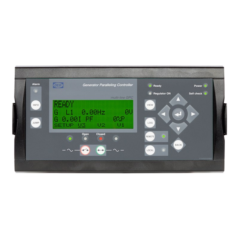
DEIF GPC-3 Generator Paralleling Controller – Synchronising, Load Sharing & Generator Protection
Pricing depends on specification, quantity and delivery location. Send your requirement and we reply with a costed quotation within 24 hours.
Quick overview
- Type: Generator paralleling controller
- Voltage: 100–690 V AC (measuring)
- Supply: 12/24 V DC
- Signal / Protocol: Modbus RTU, Profibus DP, CAN J1939, Modbus TCP/IP (options)
- Genuine productsSourced from the manufacturer or authorised channels
- Delivery across BangladeshDhaka, Chattogram and all industrial zones
- After-sales supportInstallation guidance and warranty handling
- Reply within 24 hoursCall +880 1713 552466 or email hello@argonmark.com
Specifications
| General | |
|---|---|
| Part no. | BD-1654 |
| Category | Electrical — Power & Distribution |
| Group | Electrical |
| Brand | DEIF |
| Model | GPC-3 |
| Technical | |
| Type | Generator paralleling controller |
| Voltage | 100–690 V AC (measuring) |
| Supply | 12/24 V DC |
| Signal / Protocol | Modbus RTU, Profibus DP, CAN J1939, Modbus TCP/IP (options) |
Datasheet
General
| Model | DEIF GPC-3 (Multi-line 2 Generator Paralleling Controller) |
|---|---|
| Software | Version 3.0x.x or later |
| Applications | Stand-alone, parallel with other generators, parallel to mains (can be combined); land-based |
| Generator type | Synchronous or asynchronous |
| Interfacing | Binary and analogue I/Os or serial communication; well suited to PLC-controlled systems |
| Display | Separate display unit (DU-2), on the base unit or the switchboard door; 3 m cable included; up to 2 additional displays within 200 m |
| Self-test | Cyclic self-test at start-up; errors shown in clear text and on a status relay |
| Configuration | Password-protected display menu or Multi-line 2 PC utility software (USB, free download); M-Logic micro PLC for custom logic |
| Governors | Interfaces to all governors, incl. GAC, Barber-Colman, Woodward and Cummins |
| Approvals | UL/cUL Listed to UL 508; UL/cUL Recognized to UL 2200; compliant with VDE-AR-N 4105 |
Regulation modes
| Governor (standard) | Fixed frequency, fixed power (base load), frequency droop, load sharing |
|---|---|
| AVR (with option D1) | Fixed voltage, fixed var, fixed power factor, reactive load sharing, voltage droop |
| Mode selection | Through digital inputs |
| Load sharing | Analogue P and Q load sharing lines (-5 to 0 to +5 V DC, 23.5 kΩ); CANshare digital load sharing with cable supervision (option G9) |
| Digital AVR | DEIF DVC 310 or Leroy Somer D510C (option T2) |
Measuring inputs
| AC inputs | 3 × generator voltage, 3 × generator current, 3 × busbar / mains voltage |
|---|---|
| Measuring voltage | 100 to 690 V AC ±20 % (UL/cUL: 600 V AC phase-phase); max. 0.25 VA/phase |
| Measuring current | -/1 or -/5 A AC (UL/cUL: from CTs 1–5 A); max. 0.3 VA/phase |
| Current overload | 4 × In continuously; 20 × In for 10 s (max. 75 A); 80 × In for 1 s (max. 300 A) |
| Measuring frequency | 30 to 70 Hz |
| Accuracy | Class 1.0 to IEC/EN 60688 (class 0.5 verified with option Q1); temperature coefficient ±0.2 % of full scale per 10 °C |
| Altitude | 0 to 4,000 m; derating above 2,000 m: max. 480 V AC (3W4) / 690 V AC (3W3) measuring voltage |
Power supply and I/O
| Auxiliary supply | 12/24 V DC nominal (8 to 36 V DC operational), max. 11 W; protect with 2 A slow-blow fuse |
|---|---|
| Cranking drop-out | 0 V DC for 10 ms when coming from at least 24 V DC |
| Standard I/O | 1 × status relay, 5 relay outputs, 2 pulse outputs (kWh, kvarh), 5 digital inputs (slot 1); 13 digital inputs, 4 relay outputs, P and Q load sharing lines, 2 external set-point inputs (slot 3); 4 relay outputs for GOV/AVR (slot 4) |
| Digital inputs | Optocoupler, bi-directional; ON 8–36 V DC, OFF < 2 V DC; 4.7 kΩ |
| Relay outputs | 250 V AC / 30 V DC, 5 A (UL/cUL: 250 V AC / 24 V DC, 2 A resistive); thermal 2 A continuous at 50 °C |
| Analogue outputs | 0(4)–20 mA and ±25 mA, galvanically separated, active, max. 500 Ω; update 100 ms (regulator) / 250 ms (transducer) |
| Analogue inputs | 0(4)–20 mA, 50 Ω; MPU 2–70 V AC, 10–10,000 Hz |
| Multi-inputs (M4) | 0(4)–20 mA, binary, Pt100/Pt1000 (-40 to 250 °C), RMI 0–1,700 Ω, 0–40 V DC |
| Galvanic separation | AC voltage to other I/Os 3,250 V; AC current 2,200 V; analogue outputs and binary input groups 550 V (50 Hz, 1 min) |
Environment and construction
| Operating temperature | -25 to 70 °C (with option N: -25 to 60 °C; UL/cUL: max. 55 °C surrounding air) |
|---|---|
| Storage temperature | -40 to 70 °C |
| Humidity | 97 % RH to IEC 60068-2-30 |
| Protection | Unit IP20; display IP40 (IP54 with gasket, option L), to IEC/EN 60529 |
| Mounting | DIN rail or base mount with six screws |
| Safety | EN 61010-1, over-voltage category III, 600 V, pollution degree 2; UL 508 and CSA 22.2 no. 14-05 |
| EMC / CE | EN 61000-6-2, EN 61000-6-4, IEC 60255-26 |
| Vibration / shock | IEC 60068-2-6, IACS UR E10, IEC 60255-21-1 / -21-2 (class 2); 50 g shock to IEC 60068-2-27 |
| Material | Plastics self-extinguishing to UL 94 (V1) |
| Connections | Plug terminals 0.2–4.0 mm² (AC current), 0.2–2.5 mm² (others); display 9-pole Sub-D; service port USB A-B |
| Dimensions | Base unit 220 × 165 × 115 mm (W × H × D, approx.); display 220 × 115 × 20 mm |
| Weight | Base unit 1.6 kg; display 0.4 kg |
Technical features
| Synchronising, generator control and protection in one compact unit | |
| Stand-alone, parallel with other gensets and parallel with mains operation | |
| Governor and (option D1) AVR control with active and reactive load sharing | |
| Generator and busbar protection to ANSI functions; optional mains protection (ROCOF, vector jump) | |
| M-Logic micro PLC for customised inputs, outputs and logic | |
| Event log, alarms in clear text and cyclic self-test with status relay | |
| Separate display for door mounting; up to two additional displays and five AOP-2 panels | |
| Modbus, Profibus, CAN J1939 engine communication and Ethernet options for PLC / SCADA integration |
Applications
| Synchronising and load-sharing panels for diesel and gas generator sets | |
| Captive power plants and factories running gensets in parallel with the grid | |
| Hospitals, data centres and commercial buildings with standby generators | |
| PLC-controlled multi-genset power systems |
Response times (delay set to minimum)
| Area | Function | Response time |
|---|---|---|
| Busbar | Over- / under-voltage | < 50 ms |
| Busbar | Over- / under-frequency | < 50 ms |
| Busbar | Voltage unbalance | < 200 ms |
| Generator | Reverse power | < 200 ms |
| Generator | Over-current | < 200 ms |
| Generator | Fast over-current | < 40 ms |
| Generator | Over- / under-voltage | < 200 ms |
| Generator | Over- / under-frequency | < 300 ms |
| Generator | Overload | < 200 ms |
| Generator | Current unbalance | < 200 ms |
| Generator | Voltage unbalance | < 200 ms |
| Generator | Reactive power import / export | < 200 ms |
| Generator | Overspeed | < 400 ms |
| Generator | Digital inputs | < 250 ms |
| Generator | Emergency stop | < 200 ms |
| Generator | Multi-inputs | < 800 ms |
| Generator | Wire failure | < 600 ms |
| Mains | df/dt (ROCOF) | < 130 ms (4 periods) |
| Mains | Vector jump | < 40 ms |
| Mains | Positive sequence | < 60 ms |
| Mains | Time-dependent under-voltage (Ut<) | < 50 ms |
| Mains | Under-voltage and reactive power low (UQ<) | < 250 ms |
Available variants
| Type | Variant | Description | Item no. |
|---|---|---|---|
| GPC-3 Diesel | 06 | GPC-3 Flex with display + A1 + D1 + J1 | 2912010030-06 |
| GPC-3 Diesel | 07 | GPC-3 without display + A1 + D1 | 2912010030-07 |
| GPC-3 Diesel | 08 | GPC-3 without display | 2912010030-08 |
| GPC-3 Diesel | 09 | GPC-3 Flex with display + J1 | 2912010030-09 |
Available options (ANSI numbers in brackets)
| Option | Description | Slot | Type |
|---|---|---|---|
| A1 | Mains protection: time-dependent under-voltage (27t), under-voltage and reactive power low (27Q), vector jump (78), df/dt ROCOF (81) | – | Software |
| A4 | Positive sequence, mains voltage low (27) | – | Software |
| A5 | Directional over-current (67) | – | Software |
| C2 | Generator add-on protection: negative sequence voltage (47) / current (46), zero sequence voltage (59) / current (50), power-dependent reactive power (40) | – | Software |
| D1 | Voltage control: constant voltage, reactive power and power factor; reactive load sharing; voltage droop | – | Software |
| E1 | 2 × ±25 mA outputs (GOV/AVR or transducer) | 4 | Hardware |
| E2 | 2 × 0(4)–20 mA outputs (GOV/AVR or transducer) | 4 | Hardware |
| EF2 | 1 × ±25 mA + 1 × 0(4)–20 mA outputs | 4 | Hardware |
| EF4 | 1 × ±25 mA output + 2 relay outputs | 4 | Hardware |
| EF5 | 1 × PWM output (CAT governor) + 1 × ±25 mA + 2 relay outputs | 4 | Hardware |
| EF6 | 2 × ±25 mA outputs + 1 × PWM output | 4 | Hardware |
| F1 | 2 × 0(4)–20 mA transducer outputs | 6 | Hardware |
| G9 | CANshare: digital load sharing with cable supervision, up to 4 BTBs and 5 load-share sections, dead-bus closing | 8 | Hardware |
| H2 | Modbus RTU/ASCII (RS-485) | 2 | Hardware |
| H3 | Profibus DP | 2 | Hardware |
| H5 | Engine communication: MTU (ADEC/MDEC) and CAN bus J1939 | 8 | Hardware |
| H6 | Cummins GCS | 8 | Hardware |
| H7 | CAN bus J1939: Caterpillar, Cummins, Detroit Diesel, Deutz, Iveco, John Deere, Perkins, Scania, Volvo Penta (requires M4) | 7 | Software |
| H8.x | External I/O modules | 2, 8 | Hardware |
| H9.2 | Modbus RTU/ASCII (RS-232) and GSM modem connection | 2 | Hardware |
| M4 | Engine control and protection (safety system) or I/O extension: MPU, 3 multi-inputs, 7 digital inputs, 4 relays | 7 | Hardware |
| M13.x | 7 configurable digital inputs | 6, 8 | Hardware |
| M14.x | 4 configurable relay outputs | 2, 6, 8 | Hardware |
| M15.x | 4 configurable 4–20 mA analogue inputs | 6, 8 | Hardware |
| N | Ethernet: Modbus TCP/IP, EtherNet/IP, SMS / e-mail alarms | 10 | Hardware / software |
| Q1 | Verified measurement accuracy class 0.5 | – | Other |
| T2 | Digital AVR: DEIF DVC 310 or Leroy Somer D510C | – | Software |
| Y1 | Display layout with engine and generator-breaker control (requires M4) | – | Other |
| Y11 | Display without local control buttons | – | Other |
Only one hardware option per slot; some options exclude each other (see the manufacturer's data sheet).
Accessories
| Accessory | Description | Item no. |
|---|---|---|
| Display Unit DU-2 | Standard display, direct connection to the base unit | 2912890030 |
| Additional Display Unit DU-2 (X2) | CAN bus connection to the standard display | 2912890030 |
| Additional Operator Panel AOP-1 (X3) | 16 configurable LEDs, 8 configurable push-buttons | 2912411070 |
| Additional Operator Panel AOP-2 (X4) | 16 LEDs, 8 buttons, 1 status relay, CAN bus (up to 5 per unit) | 2912411060 |
| Display gasket (L) | IP54 for the display (standard IP40) | 1134510010 |
| Display cable 3 m / 6 m (J2) / 1 m (J6) | Base unit to display | 1022040056 / 1022040057 / 1022040064 |
| USB cable 3 m (J7) | PC utility software | 1022040065 |
| Ethernet cable, crossed, 3 m (J4) | For option N | 1022040055 |
| RS-232 cable (J3) | PC utility software | 1022040044 |
Dimension drawings
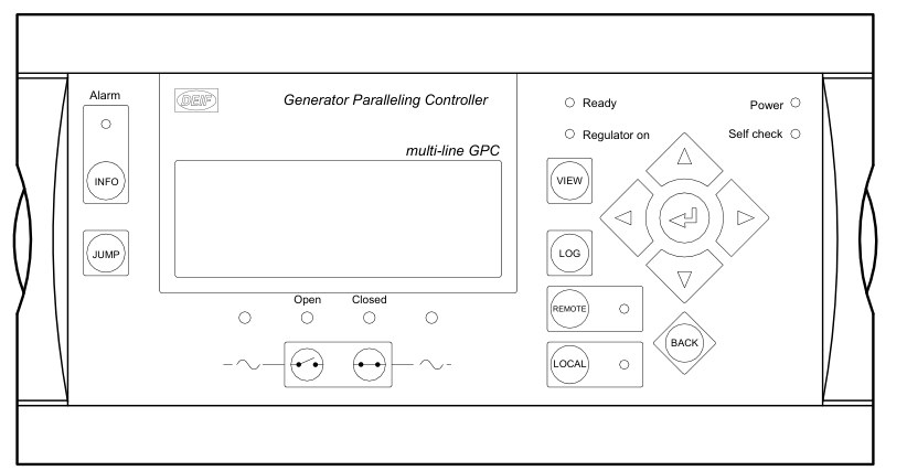
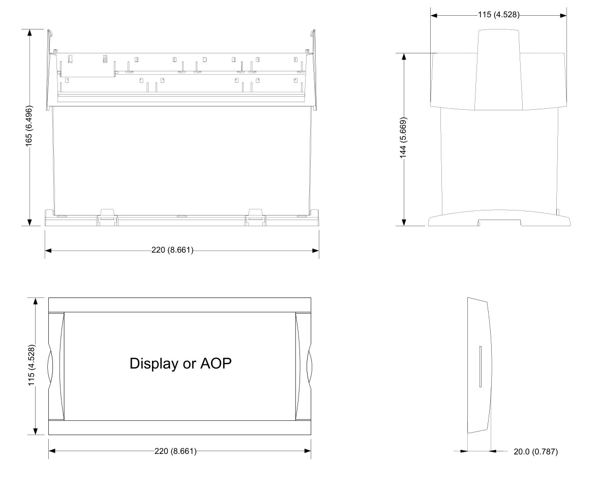
Notes
| Data from DEIF data sheet 4921240351N (GPC-3, software 3.0x.x or later). Confirm variant, options and accessories before ordering. |
Description
The DEIF GPC-3 is a compact generator paralleling controller that synchronises, controls and protects gensets in island, parallel or mains-parallel operation.
It holds all galvanically separated 3-phase measuring circuits (100–690 V AC, -/1 A or -/5 A) and controls the governor in fixed frequency, fixed power (base load), frequency droop or load sharing mode; with option D1 it also controls the AVR for fixed voltage, var, power factor, reactive load sharing and voltage droop. Protection covers generator and busbar functions (ANSI numbers), with optional mains protection (vector jump, ROCOF df/dt, time-dependent under-voltage), engine control and protection (option M4), J1939 / MTU / Cummins engine communication, CANshare digital load sharing with cable supervision, Modbus RTU, Profibus DP and Modbus TCP/IP / EtherNet/IP.
The separate display unit (DU-2, 3 m cable included) mounts on the base unit or in the switchboard door, with up to two extra displays within 200 m. Setup is by the password-protected display menu or the free Multi-line 2 PC utility software over USB, and M-Logic (micro PLC) lets inputs, outputs and logic be customised. The GPC-3 is UL/cUL listed (UL 508, recognised to UL 2200) and compliant with VDE-AR-N 4105, and suits PLC-controlled power plants, factory captive generation, hospitals, data centres and synchronising panels.
Questions & answers
Customer questions
No questions asked yet. Ask about specification, compatibility, lead time or anything else about this item.
Reviews
No reviews yet. Bought or used this item? Be the first to share your experience.
-
 Distribution transformer 25 kVA, 11kV/0.4kV, ONAN, copper wound
Price on request
-
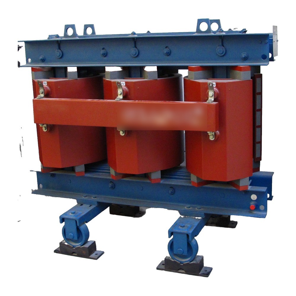 Cast resin dry-type transformer 1000 kVA, 11kV/0.4kV
Price on request
-
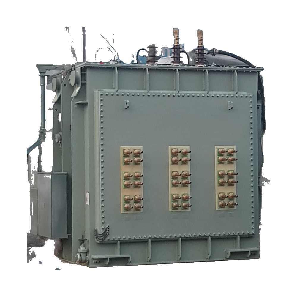 Furnace transformer 6-12 MVA for induction/arc furnace
Price on request
-
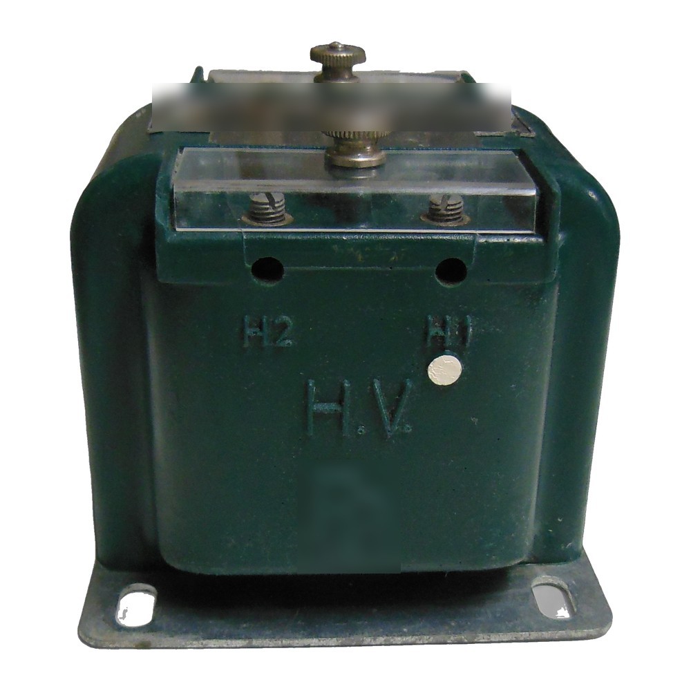 Potential/voltage transformer (PT/VT), 415V
Price on request
-
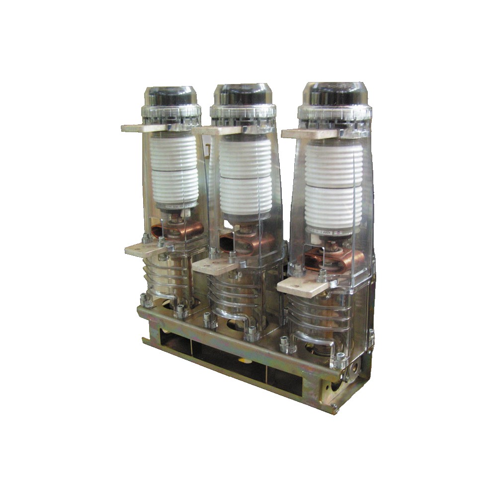 Vacuum circuit breaker (VCB) panel, 11kV, indoor metal-clad
Price on request
-
 SF6 gas-insulated switchgear (GIS) bay, 11kV
Price on request